Manufacturing insight · Sheffield
Engineering Company Sheffield
A practical guide to choosing the right combination of machining, metal forming, casting and surface-finishing processes for one-off parts, prototypes and repeat production.
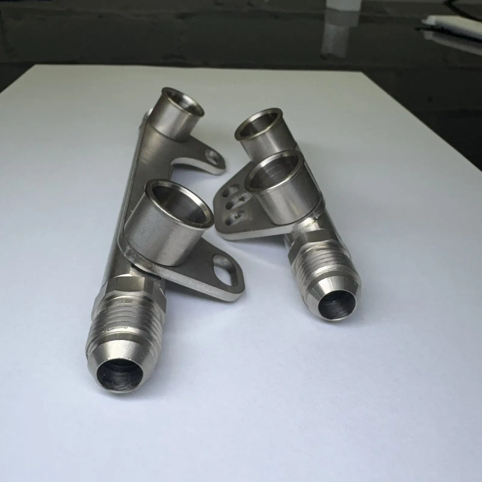
Searching for an engineering company in Sheffield often begins with a part rather than a process. A buyer may need a shaft, bracket, housing, pressing, forging or casting, but the correct route depends on material, geometry, quantity, tolerance, finish and how the component will be used.
Sheffield has a long association with metalworking and manufacturing, and modern engineering requirements frequently combine several disciplines. A laser-cut blank may need CNC machining. A forged component may require turning, heat treatment and electroplating. A stainless fabrication may need its welds dressed before electropolishing. Looking at the complete manufacturing route early helps prevent unsuitable allowances, duplicated work and a finish that conflicts with the final dimensions.
Subcontract Engineering Services gives Sheffield manufacturers, maintenance teams, product developers and trade buyers a clear point from which to discuss that route. Capability, price and lead time are confirmed against the individual drawing and specification. This matters because no single manufacturing process is automatically best for every component.
A useful starting point
Send the finished requirement, not just a process name
Include the latest drawing, material grade, quantity, critical tolerances, finish, delivery postcode and required date. If the manufacturing method is still open, explain the component’s function and expected demand.
Machining with lathes and CNC equipment
Lathe turning remains one of the most efficient ways to manufacture round components such as shafts, pins, bushes, spacers, threaded fittings and rollers. The workpiece rotates while cutting tools form outside diameters, bores, faces, tapers, grooves and threads. A manual lathe can be appropriate for repair work, simple one-offs and controlled modifications, while CNC turning supports repeatability, multiple features and production batches.
CNC milling is used when a component needs flats, slots, pockets, drilled patterns, tapped holes or three-dimensional profiles. Modern machining can work from suitable CAD data, but a 3D model should usually be accompanied by a controlled drawing. The drawing defines the details that geometry alone cannot communicate reliably: material, tolerances, thread forms, fits, surface texture, deburring, heat treatment, coating, inspection and revision.
Machining strategy affects both cost and quality. Tight tolerances should be applied to the dimensions that control fit, sealing, alignment or motion rather than every feature. Deep pockets, small internal radii, thin walls and long slender sections may add tooling, setup or inspection time. Where a part begins as a casting, forging, pressing or flame-cut blank, the machining allowance and datum surfaces must be planned before the blank is produced.
CNC production and repeatable manufacturing
For repeat orders, CNC machining offers consistent toolpaths and a stable route from approved data. Fixtures, soft jaws, inspection methods and documented setup information can reduce variation between batches. Repeatability, however, still depends on controlled input: the same material condition, drawing revision, surface treatment and acceptance criteria need to follow the part through every order.
Quantities are commercially important. A prototype may be machined directly from solid material to avoid tooling. As demand increases, a near-net-shape pressing, casting or forging may reduce material waste and cycle time before final machining. Sharing annual usage and likely batch size allows the manufacturing route to be assessed over the life of the part, rather than only against the first order.

Shaping metal efficiently
Metal pressings, forgings and castings
Pressing, forging and casting can all produce a component close to its final shape, but they create that shape in very different ways. Choosing between them requires more than comparing the outline of the finished part.
Metal pressings
Metal pressings are produced by forming sheet, strip or sometimes other stock in a press using dedicated tools. Operations may include blanking, piercing, bending, drawing, coining and forming. Pressings can be highly efficient for repeated brackets, clips, washers, covers, contacts and shallow housings. Simple parts may use single-operation tooling, while progressive tools carry strip through several stages for higher-volume production.
Tooling cost means the expected quantity and future demand should be considered early. Material thickness, grain direction, bend radius, springback, edge condition and burr direction can all influence the result. Holes or features close to a bend may distort, so the drawing needs to reflect a practical pressing sequence.
Metal forgings
Forging shapes metal through controlled compressive force, often while the material is hot. Open-die, closed-die and upset forging methods can create robust blanks for shafts, rings, levers, fittings and load-bearing components. The process can establish favourable grain flow and is often selected where strength, toughness and dependable material structure are important.
A forging normally needs appropriate draft, radii, flash allowance and machining stock. Tooling and minimum economic quantities vary with size and method. Heat treatment, scale removal, machining and testing may follow. The person-with-heated-metal photograph shown here represents the hands-on process control needed around hot-work operations.
Metal castings
Casting pours molten metal into a mould to create shapes that may be difficult or wasteful to machine from solid. Sand casting can suit larger or lower-volume parts; investment casting can produce detailed components; gravity and pressure die-casting methods may suit repeat quantities in appropriate alloys. Typical applications include housings, impellers, brackets, handles and complex bodies with internal or curved features.
Castings need design allowance for solidification, feed paths, section changes, shrinkage and subsequent machining. Material specification, pressure integrity, surface condition, heat treatment, non-destructive testing and mechanical-property requirements should be stated before quotation. A casting route should be chosen because it suits the geometry and quantity—not simply because the finished part looks castable.
Surface engineering
Electroplating and electropolishing
These processes sound similar, but one deposits material while the other removes a controlled microscopic layer. The drawing must distinguish between them and define the required result.
Electroplating
Electroplating uses an electrical process to deposit a metal coating onto a prepared component. Zinc, nickel, copper, chrome and other systems may be considered depending on corrosion protection, wear, appearance, conductivity or further processing.
Base material, coating type, thickness, finish, masking, thread allowance, hydrogen-embrittlement controls and relevant standards all need definition. Because plating adds thickness, close fits and threads may require allowance before machining.
Electropolishing
Electropolishing removes a very thin surface layer through an electrochemical process. It is commonly associated with stainless steel and can reduce microscopic peaks, improve cleanability, brighten the surface and support corrosion performance when the complete process is correctly specified.
The starting surface remains important: electropolishing is not a substitute for removing deep scratches, heavy weld defects or poor fabrication. Material grade, pre-finishing, masking, dimensional sensitivity and the desired acceptance standard should be agreed first.
Other finishes
Depending on the component and environment, the route may instead use powder coating, wet paint, anodising, passivation, black oxide, galvanising, polishing, bead blasting or specialist thermal and plasma coatings.
Finish selection should consider service temperature, outdoor exposure, chemicals, hygiene, wear, electrical contact, colour, appearance and whether later welding or assembly is required.
Beyond a single operation
Other relevant manufacturing methods
Many successful components pass through several carefully ordered operations. The manufacturing plan should protect critical features and avoid applying a treatment too early.
Laser and plasma cutting
Profile plate and sheet for brackets, guards, bases, blanks and fabricated assemblies before bending or machining.
Sheet-metal fabrication
Combine folding, rolling, punching, welding and assembly for enclosures, frames, trays, ducts and guards.
Welding
Join steel, stainless steel or aluminium components using a process and procedure appropriate to material and duty.
Heat treatment
Control hardness, strength, toughness, stress or machinability through a defined thermal cycle and material condition.
Grinding and finishing
Achieve close size, geometry or surface texture after machining or heat treatment where the specification requires it.
Assembly and inspection
Bring components together with agreed identification, dimensional checks, certificates, reports and packaging.
Method selection
How an engineering company chooses the right process
The most suitable method balances technical performance with total manufacturing cost. That balance changes as quantity, material and design evolve. A one-off housing might be machined from solid stock, a short run might use a fabricated or sand-cast blank, and a stable high-volume requirement might justify dedicated casting or pressing tools.
| Requirement | Methods to consider | Details that matter |
|---|---|---|
| Round precision parts | Lathe turning, CNC turning, grinding | Fits, concentricity, threads, surface finish and batch size |
| Repeat sheet components | Laser cutting, punching, pressings, folding | Tooling budget, bend detail, burr direction and annual demand |
| Strong load-bearing blanks | Forging followed by heat treatment and machining | Grain flow, machining allowance, testing and mechanical properties |
| Complex near-net shapes | Sand, investment or die casting | Alloy, section thickness, shrinkage, integrity and quantity |
| Corrosion-resistant surface | Electroplating, electropolishing or another coating | Base material, exposure, thickness, masking and acceptance standard |
Design for manufacture before production
Early review can often simplify a part without changing its function. Standard material sizes, accessible tool paths, realistic radii, sensible tolerances and a clear datum scheme may reduce setups and scrap. For pressings, castings and forgings, the design must also accommodate how the tool opens, how metal flows and where material is trimmed or fed.
Process order is equally important. Welding may distort a frame, so critical faces could be machined afterwards. Heat treatment can alter size, meaning grinding stock may be required. Electroplating adds thickness, while electropolishing removes a small amount. A coordinated route records which dimensions apply at which stage.
Quality, traceability and documentation
Requirements for material certificates, traceability, first-off approval, dimensional reports, coating certificates, heat-treatment records, non-destructive testing or certificates of conformity should be included before manufacture. Evidence often needs to be captured during the work and cannot be reconstructed safely after delivery.
Safety-critical, structural, pressure, lifting, food, medical or regulated applications may need specific standards, approved suppliers and validated procedures. These requirements must be stated directly rather than assumed from a general description of the component.
A faster technical review
What to send with your engineering enquiry
A well-defined enquiry gives an engineering company the information needed to assess method, availability, cost and lead time without filling gaps with assumptions.
- Drawing and modelLatest revision of the PDF drawing plus STEP, DXF or other useful CAD data.
- MaterialExact grade, condition, stock form and any certification or traceability requirement.
- QuantityImmediate batch, annual demand, repeat frequency and any prototype requirement.
- Critical featuresFits, threads, tolerances, surface texture and dimensions that control function.
- Complete routeMachining, forming, welding, treatment, coating, assembly, marking and packaging.
- Commercial detailDelivery postcode, required date, inspection records and purchasing contact.
Engineering Company Sheffield
Have a component or manufacturing requirement to discuss?
Email the drawing and project details to info@subcontractengineeringservices.co.uk. If a conversation would be easier, request a call back and include your phone number and a suitable time.